CHAPTER
1
INTRODUCTION
1.1
|
Project Background
|
Now
days, people do not know how much electrical energy use in a month because
there is no system to alert them. So, with this Monthly Electric Bill Saving
System (MEBSS) project, it will help people to know how much they use and also
they can set the amount (RM) they want in electricity bill at the end of the
month. It has an LCD that display everything such as energy usage in kWh unit
and the bill need to pay in RM unit.
This system already converts from energy usage kWh to a billing in
Ringgit Malaysia (RM) by referring a tariff domestic from TNB. They also can
set the amount (RM) in this MEBS system. The buzzer will give sound in that
house if the amount is reached. If it reach early of the month they can add another amount
(RM) in MEBS System. With this system they can budget for electrical bill and
save money.
For
example:
If Mr. A wants to pay only RM20 at the end of
the month, so Mr. A need to set RM20 in MEBSS. But if the MEBSS trip before the
end of the month, then Mr A need to add the amount at the MEBSS. Let say, Mr. A
add another RM10, so, the calculation for that month is RM20 (early seating) +
RM10 (after setting) = RM30. So Mr. A will know that he needs to pay RM30 for
electrical bill.
This
project is fully controlled by embedding system a program that program
in microcontroller PIC 16f877a. An embedded
system is a special-purpose system in which the computer is completely
programmed with or dedicated to the device or system it controls. Unlike a
general-purpose computer, such as a personal computer, an embedded system
performs one or a few predefined tasks, usually with very specific
requirements. Since the system is dedicated to specific tasks, design engineers
can optimize it, reducing the size and cost of the product. Embedded systems are
often mass-produced, benefiting from economies of scale.
1.2
|
Project
Statment
|
||
In every house the energy meter only shows the watt usage per
hour. That is why the consumer always did not know how much electrical energy
use in a month because there is no system to alert them. Beside that the
consumer did not know how to read the energy meter. So, the consumer did not
know how much they need to pay for the electric bill by the end of the month.
Other than that, because of the consumer did not how to read the energy meter,
it is so hard for them to budget their electrical bill.
So, with this Monthly Electric Bill Saving System
(MEBSS) project, it will help people to know how much they use and also they
can set the amount (RM) they want in electricity bill at the end of the month.
It has LCD that display everything such as energy usage in kWh unit and the
bill need to pay in RM unit. This system already converts from energy
usage kWh to a billing in Ringgit Malaysia (RM) by referring a tariff domestic
from TNB. They also can set the amount (RM) in this MEBS system. The buzzer
will give sound in that house if the amount is reached. If it reach early of
the month they can add another amount (RM) in MEBS System. With this system they
can budget for electrical bill and save money.
1.3 Objective
To acknowledge the consumer regarding their electric
bill they need to pay by the end of the month. To make the consumer more easier
to know the usage of energy in digit number from the LCD display. The
consumer can budget for electric bill by setting the amount to system and after
reaching the amount the system will give alert to consumer.
CHAPTER
2
LITERATURE
REVIEW
2.1
|
Project Background
|
After doing a research, there have
many informative and project that has connected to the proposed project. In a
present day there already change from the analog energy meter to a digital
energy meter in a certain place and the other places still have used the analog
energy meter. Now, according to Md. Mejbaul Haque project that I have research. He creates a single phase digital prepaid energy meter
based on two microcontrollers and a single phase energy meter IC. His digital
prepaid energy meter does not have any rotating parts. The energy consumption
is calculated using the output pulses of the energy meter chip and the internal
counter of microcontroller (ATmega32). According to research, his
microcontroller (ATtiny13) is used as a smart card and the numbers of units
recharged by the consumers are written in it. A relay system has been used
which either isolate or establishes the connection between the electrical load
and energy meter through the supply mains depending upon the units present in
the smart card. Energy consumption (kWh), maximum demand (kW), total unit
recharged (kWh) and the rest of the units (kWh) are stored in the ATmega32 to
ensure the accurate measurement even in the event of an electrical power outage
that can be easily read from a 20×4 LCD. As soon as the supply is restored,
energy meter restarts with the stored values. A single phase prepaid energy
meter prototype has been implemented to provide measurement up to 40A load
current and 230V line to neutral voltage.Necessary program for microcontrollers
are written in c-language and compiled by Win-AVR libc compiler.
For
my opinion, using a card reader is hard for us to reload the prepaid card if
the card is empty. Need to make sure the card has credit, if we want use an
electrical. For my project, the most important contributions of other
related projects/findings for my project is to make sure the
consumer know how much they use the energy, besides this project is already
convert from energy usage (kWh) to Ringgit Malaysia (RM),so the consumer will
know how much for electric bill in a month that need to pay. Other than that,
this project have saving system, so they set the amount if they want to budget
in an electric bill by set how much they want to pay into the system.
2.2
|
Development of Achitecture
|
||
The system architecture of microcontroller based
single phase digital prepaid energy meter for improved metering system is shown
in figure 1.

Fig. 1 Prepaid energy
metering system
The energy metering system consists of Energy Meter
chip, Microcontroller, Voltage and Current controlling unit, Smart cart, Relay
and Liquid Crystal Display (LCD).
·
Energy Meter IC generally produces
electrical pulses proportional to the power consumed by the consumer and the
power supply of microcontroller.
·
Microcontroller calculates the energy
consumed by the consumer utilizing the output of Energy Meter Chip and programs
loaded on the microcontroller.
·
Voltage and Current controlling unit
feeds the actual current and voltage of load connected to consumer side to the
energy meter chip.
·
Smart Card interfaces with the
microcontroller unit in which the number of units recharged by the consumer are
written.
·
Relay mainly performs the opening and
closing of a connection between energy meter and load through supply mains
depending upon the number of units present in the smart card at a moment.
·
Liquid Crystal Display shows the energy
consumption, number of unit recharged by the consumer, rest of the unit and
maximum demand.
The energy billing system is shown in figure 2. The
energy billing system mainly consists of a user operated PC, USB Burner circuit
and Smart card.
2.3 Summary of literature review
This paper has demonstrated for
measuring the electrical energy consumption of an electrical load for two wire
distribution systems with the proposed energy meter as an alternative to the
conventional electromechanical meters. This microcontroller based energy meter
prototype has been implemented to provide measurement up to 40 A load current
from a 230 V line to neutral voltage. The proposed energy meter is capable of
measuring energy consumption for all loads conditions i.e. power factor and
non-sinusoidal voltage and current waveforms. It does not posses any rotating
parts that help in the prevention of meter tampering, which is an attractive
feature for the utilities. The proposed energy meter includes a “no load
threshold” feature that will eliminate any creeping effects in the meter. In
addition, the process of reading the energy consumption is facilitated by the
LCD display that is simpler than that for the analog meters which reduces human
errors while noting down the meter reading. This energy meter has the potential
to change the future of the energy billing system in Bangladesh. The energy
billing system may help the energy distribution companies to reduce costs and
increase profits, to improve metering and billing accuracy and efficiency, and
to contribute the energy in a sustainable way. To recharge the microcontroller
chip, it must be taken to the server terminal or unit. The energy billing
system provides employment for nearly 2-3 people in every server terminal for
jobs like recharging the smart card and processing the distribution of power in
a convenient way. In future, mode of recharging the smart card can be improved
by wireless communication between the server terminal and energy meter unit.
CHAPTER
3
METHADOLOGY
3.1
|
Electronic
|
3.1.1
Power Supply

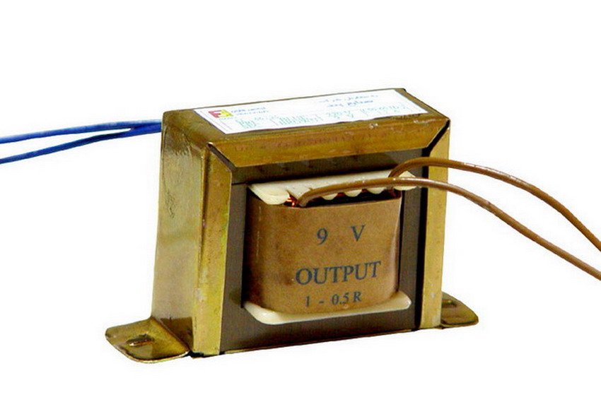
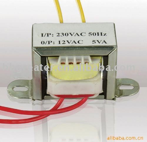
3.1.1.1 Transformer to step down
voltage from 240V to 12V.
A transformer consists of two coils (often called 'windings')
linked by an iron core, as shown in the figure below. There is no electrical
connection between the coils, instead they are linked by a magnetic field
created in the core.

Step-down transformers
Step down transformers is to reduce a
voltage. Most power supplies use a step-down transformer to reduce the
dangerously high mains voltage to a safer low voltage. The
input coil is called the primary and the output coil is called the
secondary.
For this project, it will use a step down
transformers that give output 9V or 12V as picture below.
The ratio of the number of turns on each coil,
called the turn’s ratio, determines the ratio of the voltages. A step-down
transformer has a large number of turns on its primary (input) coil which is
connected to the high voltage mains supply, and a small number of turns on its
secondary (output) coil to give a low output voltage.
Below are transformers formula,
Turns ratio = Vp/ VS = Np/NS
Power Out= Power In
VS X IS=VP X
IP
Vp
= primary (input) voltage
Np
= number of turns on primary coil
Ip
= primary (input) current
Transformers have two great advantages over other methods of
changing voltage:
1.
They provide total electrical isolation between the input and
output, so they can be safely used to reduce the high voltage of the mains
supply.
2.
Almost no power is wasted in a transformer. They have a high
efficiency (power out / power in) of 95% or more.
3.1.1.2 Bridge rectifier to convert
from AC to DC voltage.
A Bridge Rectifier ( Full wave Rectifier )
The circuit in figure 3 addresses the second of
these problems since at no time is the output voltage 0V. This time four
diodes are arranged so that both the positive and negative parts of the AC
waveform are converted to DC. The resulting waveform is shown in figure
4.


When the AC input is positive, diodes A and B
are forward-biased, while diodes C and D are reverse-biased. When the AC
input is negative, the opposite is true - diodes C and D are forward-biased,
while diodes A and B are reverse-biased.
One disadvantage of the full-wave rectifier is
that there is a voltage loss of 1.4V across the diodes. Why not 2.8V as
there are four diodes, that is because there is only two of the diodes are
passing current at any one time.
While the full-wave rectifier is an improvement
on the half-wave rectifier, its output is still not suitable as a power supply
for most circuits since the output voltage still varies between 0V and
Vs-1.4V. So, if you put 12V AC in, you will 10.6V DC out.
The formula Bridge full wave Rectifier is,
Full
wave Bridge
|
||
Number
of diodes
|
4
|
|
PIV
of diodes
|
Vm
|
|
D.C
output voltage
|
2Vm/phi
|
|
Vdc,at
no-load
|
0.636Vm
|
|
Ripple
factor
|
0.482
|
|
Ripple
frequency
|
2f
|
|
Rectification
efficiency
|
0.812
|
|
Transformer
Utilization
Factor(TUF)
|
0.812
|
|
RMS
voltage Vrms
|
Vm/√2
|
|
A bridge rectifier makes use of four diodes in a bridge arrangement to achieve full-wave rectification. This is a widely used configuration, both with individual diodes wired as shown and with single component bridges where the diode bridge is wired internally. So, in this project it will use 4 x 1N4001 diode (as picture below).

Diode type 1N4001
3.1.1.3 Filter
This is why the 'smoothing' block is required. Its because
the output come from bridge rectifier is not suitable for power supply. So to
give the output more smooth we use filtering circuit by using only one
capacitor as shown in figure 1 below.
The output waveform in figure 2 shows how smoothing works.
During the first half of the voltage peaks from the rectifier, when the voltage
increases, the capacitor charges up. Then, while the voltage decreases to
zero in the second half of the peak, the capacitor releases its stored energy
to keep the output voltage as constant as possible. Such a capacitor is
called a 'smoothing' or 'reservoir' capacitor when it is used in this
application.

If the voltage peaks from the rectifier were not continually
charging up the capacitor, it would eventually discharge and the output voltage
would decrease all the way down to 0V. The discharging that does occur
between peaks gives rise to a small 'ripple' voltage. The amount of
ripple is affected by a combination of three factors:
- The
value of the capacitor. The larger the capacitor value, the more charge
it can store, and the slower it will discharge. Therefore, smoothing
capacitors are normally electrolytic capacitors with values over 470μF.
- The
amount of current used by the circuit. If the circuit connected to the power supply
takes a lot of current, the capacitor will discharge more quickly and
there will be a higher ripple voltage.
- The
frequency of the peaks.
The more frequent the voltage peaks from the rectifier, the more often the
capacitor will be charged, and the lower the ripple voltage will be.
To
calculate the ripple voltage, it will use this formula below.
Vr = the
ripple voltage in Volts
I
= the current taken by the circuit in Amps
C
= the value of the smoothing capacitor in Farads
F
=the frequency of the peaks from the full-wave rectifier, in Hertz.
The
ripple voltage should not be more than 10% of Vs - if it is, increase the value
of the smoothing capacitor.
So
in this project, the value capacitor for filter circuit is 470uF ( as the
picture below ).

Capacitor
470uF
3.1.1.4 IC
Regulated (LM7805) to regulate the voltage 5V to supply to
Microcontroller.
There are many types of regulator IC and each
type will have different pin-outs and will need to be connected up slightly
differently. Therefore, this article will only look at one of the common
ranges of the regulator, the 78xx series.
There are seven regulators in the 78xx series,
and each can pass up to 1A to any connected circuit. There are also
regulators with similar type numbers that can pass a higher or lower current,
as shown in the table below. In addition, variable regulators are available,
as are regulators that can provide negative regulation voltages for circuits
that require them.
Type Number
|
Regulation Voltage
|
Maximum Current
|
Minimum Input Voltage
|
|||
78L05
|
+5V
|
0.1A
|
+7V
|
|||
78L12
|
+12V
|
0.1A
|
+14.5V
|
|||
78L15
|
+15V
|
0.1A
|
+17.5V
|
|||
78M05
|
+5V
|
0.5A
|
+7V
|
|||
78M12
|
+12V
|
0.5A
|
+14.5V
|
|||
78M15
|
+15V
|
0.5A
|
+17.5V
|
|||
7805
|
+5V
|
1A
|
+7V
|
|||
7806
|
+6V
|
1A
|
+8V
|
|||
7808
|
+8V
|
1A
|
+10.5V
|
|||
7812
|
+12V
|
1A
|
+14.5V
|
|||
7815
|
+15V
|
1A
|
+17.5V
|
|||
7824
|
+24V
|
1A
|
+26V
|
|||
78S05
|
+5V
|
2A
|
+8V
|
|||
78S09
|
+9V
|
2A
|
+12V
|
|||
78S12
|
+12V
|
2A
|
+15V
|
|||
78S15
|
+15V
|
2A
|
+18V
|
|||
If using a regulator after the smoothing block
of the power supply, then not need to worry about the ripple voltage, since the
whole point of using a regulator is to get a stable, accurate, known voltage
for your circuits. However, if the ripple voltage is too large and the input
voltage to the regulator falls below the regulated voltage of the regulator,
then of course the regulator will not be able to produce the correct regulated
voltage. In fact, the input voltage to a regulator should usually be at
least 2V above the regulated voltage. In our power supply circuit, the
input to the 7805 regulator is around 12V, and the regulation voltage is 5V, so
there is plenty of headroom. The maximum input voltage to any 78xx
regulator is 30V.
Filtering is performed by a large value
electrolytic capacitor connected across the DC supply to act as a reservoir,
supplying current to the output when the varying DC voltage from the rectifier
is falling. The capacitor charges quickly near the peak of the varying DC, and
then discharges as it supplies current to the output. Filtering significantly
increases the average DC voltage to almost the peak value (1.4 × RMS values).
To calculate the value of the capacitor (C),
C = ¼*√3*f*r*Rl
Where,
f = supply frequency,
r = ripple factor,
Rl = load resistance
The 78xx, 78Mxx, and 78Sxx regulators all have
the pin-out shown in the left of figure 1. The 78Lxx series, shown in the right
of figure 1. The connection circuit of regulator 78xx, as shown in figure 2.
For this project, it use 7805 because give regulated output is 5V and
the micro controller only need 5V of source.


IC regulator LM7805
3.1.2 Micro-chipAD7755(
energy ic)
This
application describes a low-cost, high-accuracy watt-hour meter based on the
AD7755. The meter described is intended for use in single phase, two wire
distribution systems. However the design can easily be adapted to suit specific
regional requirements, for example in the Malaysia power is usually distributed
to residential customers as single-phase, three-wire. The AD7755 is a low-cost,
single-chip solution for electrical energy measurement. The AD7755 is comprised
of two ADCs, reference circuit, and all the signal processing necessary for the
calculation of real (active) power. The AD7755 also includes the direct drive
capability for electromechanical counters (i.e., the energy register), and has
a high-frequency pulse output . The AD7755 provides direct drive capability for
this type of counter. The AD7755 also provides a high-frequency output which
give the output for 100 pulse per 1kWh.

The
test circuit from datasheet AD7755

The
picture of AD7755
Design Calculations
Design parameters:
Line voltage = 220 V (nominal)
IMAX = 40 A (Ib = 5 A)
Counter = 100 imp/kWh
Meter constant = 3200 imp/kWh
Shunt size = 350 μΩ
100 imp/hour = 100/3600 sec = 0.027777 Hz
Meter will be calibrated at Ib (5A)
Power dissipation at Ib = 220 V × 5 A = 1.1 kW
Frequency on F1 (and F2) at Ib = 1.1 × 0.027777 Hz
= 0.0305555 Hz
Voltage across shunt (V1) at Ib = 5 A × 350 μΩ = 1.75 mV.
To select the F1–4 frequency for Equation 1 see the AD7755 data
sheet, Selecting a Frequency for an Energy Meter Application section. From Tables
V and VI in the AD7755 data sheet it can be seen that the best choice of
frequency for a meter with IMAX = 40 A is 3.4 Hz (F2). This frequency selection
is made by the logic inputs S0 and S1—see Table II in the AD7755 data sheet.
The CF frequency selection (meter constant) is selected by using the logic
input SCF. The two available options are 64 F1(6400 imp/kWh) or 32 × F1(3200
imp/kWh). For this design, 3200 imp/kWh is selected by setting SCF logic low.
With a meter constant of 3200 imp/kWh and a maximum current of 40 A, the
maximum frequency from CF is 7.82 Hz. Many calibration benches used to verify
meter accuracy still use optical techniques. This limits the maximum frequency
that can be reliably read to about 10 Hz. The only remaining unknown from equation
1 is V2 or the signal level on Channel 2 (the voltage channel).
From Equation 1 on the
previous

Therefore, in order to calibrate the meter the line voltage needs
to be attenuated down to 248.9 mV.
The data sheet AD7755 is in APPENDIX
3.1.3 Microcontroller
PIC16f877a (brain system)
3.1.3.1 Introduction
This section is the control unit of the whole
project. It basically consists of a Micro controller with its associated
circuitry like Crystal with capacitors, Reset circuitry, Pull up
resistors (if needed) and so on. The Micro controller forms the heart of the
project because it controls the devices being interfaced and communicates with
the devices according to the program being written.
A Micro controller consists of a powerful CPU
tightly coupled with memory RAM, ROM or EPROM), various I / O features such as
Serial ports, Parallel Ports, Timer/Counters, Interrupt Controller, Data
Acquisition interfaces-Analog to Digital Converter (ADC), Digital to Analog
Converter (ADC), everything integrated onto a single Silicon Chip.
Micro controller
has memory such as RAM, ROM or EPROM and peripherals on a
single chip so development of a similar system with a micro controller reduces
PCB size and cost of the design.
3.1.3.2 Micro controller
use in the project PIC16f877A
This devices are
available in 40-pin packages is shown as picture below.

PIC16f877a
This microcontroller Pic16f877a is a
main component in the system. It will be programmed in C language to do the
whole operation in the system. All the description on the Pic16f877a can be see
on data sheet appendix ( ) . Each
pin of the pic16f877a will do a
different operation. For PORT A it use to count the pulse coming from energy ic
AD7755. For PORT B it is use to send data interrupt function and keypad number
to LCD. For PORT C use as push button. For PORT D is use as LCD.
Device features.

Port Function.

3.1.4 Liquid Clear Display (LCD)
LCD will display everything such as energy
usage in kWh unit and the bill need to pay in RM unit.

In
8 bit mode all the Data lines DB0 to DB7 are being used for transferring the
data to the LCD but in 4-bit mode only 4 line form DB4 to DB7 are being used to
transfer the 8 bit wide data in two
peaces one after another . We cannot display any data on the LCD until all the
required internal command registers of the LCD are not being properly initialized.

3.1.5 Keypad 3x4


Description
of Basic Operation
The
Keypads are low-voltage, microprocessor-based user interfaces designed to
operate with a host controller. The devices consist of twelve (12)
touch-sensitive buttons that operate via patented TouchCell™ Field-Effect touch technology. The buttons are arranged in
a standard 3x4 numeric keypad layout.
The
Keypads are provided with the following features:
•
Backlit touch-sensitive keypads
•
Audio beeper feedback
This
keypad will help the consumer to key in their amount in the system, so that the
system will know how much amount consumer want for their electric bill.
3.1.5.1 MM74C922
Keypad 3x4 will interface with mm74c922 as to give the output to
the lcd. Below are the connection for the interface.
From the block diagram
above we know that the keypad will give output which is A,B,C and D if key pressed. The output will based on the
truth table. From the output truth table it will combine with the ASCI code
from LCD and display numeric number in the LCD.

3.1.6 Relay


A
relay is use to trigger the system to send the signal in automatic operation
which can be control by microcontroller system.
A
relay is an electrically operated switch. Current flowing through the coil of
the relay creates a magnetic field which attracts a lever and changes the
switch contacts. The coil current can be on or off so relays have two switch
positions and most have double throw (changeover) switch contacts as shown in
the diagram.
Relays
allow one circuit to switch a second circuit which can be completely separate
from the first. For example a low voltage battery circuit can use a relay to
switch a 230V AC mains circuit. There is no electrical connection inside the
relay between the two circuits, the link is magnetic and mechanical.
The
coil of a relay passes a relatively large current, typically 30mA for a 5V/12V
relay, but it can be as much as 100mA for relays designed to operate from lower
voltages. Most ICs (chips) cannot provide this current and a transistor is
usually used to amplify the small IC current to the larger value required for
the relay coil.
Relays
are usuallly SPDT or DPDT but they can have many more sets of switch contacts,
for example relays with 4 sets of changeover contacts are readily available.
For further information about switch contacts and the terms used to describe
them please see the page on switches. Most relays are designed for PCB mounting
but you can solder wires directly to the pins providing you take care to avoid
melting the plastic case of the relay.

The
relay's switch connections are usually labelled COM, NC and NO:
COM
= Common, always connect to this, it is the moving part of the switch.
NC
= Normally Closed, COM is connected to this when the relay coil is off.
NO
= Normally Open, COM is connected to this when the relay coil is on.
3.1.6.1 ULN2003
This
relay is interface by ULN2003 which give the signal from microcontroller to the
relay. Below picture are shown the operation of ULN2003.


When
the signal from microcontroller is low the relay will switch on the bulb. When
the signal is high the relay will switch off the bulb.
The
ULN2003 is a monolithic high voltage and high current transistor arrays. It
consists of seven NPN pairs that feature high-voltage outputs with common-cathode
clamp diode for switching inductive loads. The collector-current rating of a
single pair is 500mA. The pairs may be paralleled for higher current
capability. Applications include relay drivers, hammer drivers, lamp drivers, display
drivers (LED gas discharge),line drivers, and logic buffers. The ULN2003 has a
2.7kW series base resistor for each pair for operation directly with TTL or 5V
CMOS devices.


This are the diagram for ULN2003 in datasheet.
3.1.7 Buzzer
A
buzzer or beeper is an audio signaling device, which may be mechanical,
electromechanical, or piezoelectric. Typical uses of buzzers and beepers
include alarm devices, timers and confirmation of user input such as a mouse
click or keystroke.
In
this project the buzzer will act and make a sound to alert the consumer that
their amount is reach.

3.2
|
Electrical
|
||
3.2.1 Single phase Meter
Single phase induction type energy meter is also
popularly known as watt-hour meter. Single phase energy meter is a device that
measures the amount of electric energy consumed by a residence, business, or an
electrically powered device. It typically calibrated in billing units, the most
common one being the kilowatt hour (kWh). Periodic readings of electric meters
establish billing cycles and energy used during a cycle. Single phase energy
meter are consists of following components:
1. Driving system
2. Moving system
3. Braking system and
4. Registering system


Connection Diagram of Single phase energy meter
3.2.1.1 Driving system
It
consists of two electromagnets, called “shunt” magnet and “series” magnet, of
laminated construction. A coil having large number of turns of fine wire is
wound on the middle limb of the shunt magnet.
This
coil is known as “pressure or voltage” coil and is connected across the supply
mains. This voltage coil has many turns and is arranged to be as highly
inductive as possible. In other words, the voltage coil produces a high ratio
of inductance to resistance.

An adjustable copper shading ring are provided on
the central limb of the shunt magnet to make the phase angle displacement
between magnetic field set up by shunt magnet and supply voltage is
approximately 90 degree.
The copper shading bands are also called the power
factor compensator or compensating loop. The series electromagnet is energized
by a coil, known as “current” coil which is connected in series with the load
so that it carry the load current. The flux produced by this magnet is proportional
to, and in phase with the load current.
3.2.1.2 Moving system
The moving system essentially consists of a light
rotating aluminum disk mounted on a vertical spindle or shaft. The shaft that
supports the aluminum disk is connected by a gear arrangement to the clock
mechanism on the front of the meter to provide information that consumed energy
by the load.
The time varying (sinusoidal) fluxes produced by
shunt and series magnet induce eddy currents in the aluminum disc. The
interaction between these two magnetic fields and eddy currents set up a
driving torque in the disc.
The number of rotations of the disk is therefore
proportional to the energy consumed by the load in a certain time interval and
is commonly measured in kilowatt-hours (Kwh).
3.2.1.3 Braking system
Damping of the disk is provided by a small permanent
magnet, located diametrically opposite to the a.c magnets. The disk passes
between the magnet gaps. The movement of rotating disc through the magnetic
field crossing the air gap sets up eddy currents in the disc that reacts with
the magnetic field and exerts a braking torque.
By changing the position of the brake magnet or
diverting some of the flux there form, the speed of the rotating disc can be
controlled.
3.2.1.4 Registering or Counting
system


The registering or counting system essentially
consists of gear train, driven either by worm or pinion gear on the disc shaft,
which turns pointers that indicate on dials the number of times the disc has
turned. The energy meter thus determines and adds together or integrates all
the instantaneous power values so that total energy used over a period is thus
known.
3.2.2
Distribution Board
A distribution board (or panel board) is a component
of an electricity supply system which divides an electrical power feed into
subsidiary circuits, while providing a protective fuse or circuit breaker for
each circuit, in a common enclosure. Normally, the protective are include is
the main switch, and in recent boards, one or more Residual-current devices
(RCD) or Residual Current Breakers with Overcurrent protection (RCBO), will
also be incorporated. There are also have the Miniature Circuit Breaker as the
switch circuit.


3.2.2.1
Electrical protective device
Equipment applied to electric power systems to
detect abnormal and intolerable conditions and to initiate appropriate
corrective actions. These devices include lightning arresters, surge
protectors, fuses, and relays with associated circuit breakers, recloses, and
so forth.
The disturbances in the normal operation of a power
system occur. These may be caused by natural phenomena, such as lightning,
wind, or snow; by falling objects such as trees; by animal contacts or chewing;
by accidental means traceable to reckless drivers, inadvertent acts by plant
maintenance personnel, or other acts of humans; or by conditions produced in
the system itself, such as switching surges, load swings, or equipment
failures. Protective devices must therefore be installed on power systems to
ensure continuity of electrical service, to limit injury to people, and to
limit damage to equipment when problem situations develop. Protective devices
are applied commensurately with the degree of protection desired or felt
necessary for the particular system.


The protective use in this project is
1.
Main Switch
2.
Residual Current Circuit Breaker (RCCB)
3.
Miniature Circuit Breaker ( MCB )
3.2.2.1.1
Switch Fuse 32A


The
switch fuse is used as the main switch in low voltage switchgears in the
industry for distributing power and protecting motors, cables and other devices
against short circuits and overloads.
3.2.2.1.2
RCCB
A residual-current circuit breaker (RCCB), is an
electrical wiring device that disconnects a circuit whenever it detects that
the electric current is not balanced between the energized conductor and the
return neutral conductor. Ground Fault Condition is defined as: An
unintentional, electrically conducting connection between an ungrounded
conductor of an electrical circuit and the normally non-current-carrying
conductors, metallic enclosures, metallic raceways, metallic equipment or
earth. Such an imbalance may indicate current leakage through the body of a
person who is grounded and accidentally touching the energized part of the
circuit. A lethal shock can result from these conditions. RCCBs are designed to
disconnect quickly enough to prevent injury caused by such shocks. They are not
intended to provide protection against overcurrent (overload) or short-circuit
conditions.


RCCB
is operate by measuring the current balance between two conductors using a
differential current transformer. This measures the difference between the
current flowing through the live conductor and that returning through the
neutral conductor. If these do not sum to zero, there is a leakage of current
to somewhere else (to earth/ground, or to another circuit), and the device will
open its contacts.
Residual
current detection is complementary to over-current detection. Residual current
detection cannot provide protection for overload or short-circuit currents,
except for the special case of a short circuit from live to ground (not live to
neutral).

The incoming supply and the neutral conductors are
connected to the terminals at (1) and the outgoing load conductors are
connected to the terminals at (2). The earth conductor (not shown) is connected
through from supply to load uninterrupted.
When the reset button (3) is pressed the contacts
((4) and hidden behind (5)) close, allowing current to pass. The solenoid (5)
keeps the contacts closed when the reset button is released. The sense coil (6)
is a differential current transformer which surrounds (but is not electrically
connected to) the live and neutral conductors. In normal operation, all the
current down the live conductor returns up the neutral conductor. The currents
in the two conductors are therefore equal and opposite and cancel each other
out.
Any fault to earth (for example caused by a person
touching a live component in the attached appliance) causes some of the current
to take a different return path which means there is an imbalance (difference)
in the current in the two conductors (single phase case), or, more generally, a
nonzero sum of currents from among various conductors (for example, three phase
conductors and one neutral conductor).
This difference causes a current in the sense coil
(6) which is picked up by the sense circuitry (7). The sense circuitry then
removes power from the solenoid (5) and the contacts (4) are forced apart by a
spring, cutting off the electricity supply to the appliance.
The device is designed so that the current is
interrupted in milliseconds, greatly reducing the chances of a dangerous
electric shock being received.
The test button (8) allows the correct operation of
the device to be verified by passing a small current through the orange test
wire (9). This simulates a fault by creating an imbalance in the sense coil. If
the RCD does not trip when this button is pressed then the device must be
replaced.
3.2.2.1.3 MCB

Circuit
breakers are electrical switching devices for protecting and controlling the
electricity supply to respective electrical circuits. Circuit breakers protect
electrical circuitry from damage due to an overcurrent condition, such as an
overload condition or a relatively high level short circuit or fault condition.
Electrical systems in residential, commercial and industrial applications
usually include a panelboard for receiving electrical power from a utility
source. The electrical power is then delivered from the panelboard to
designated branch circuits supplying one or more loads.
Overload
protection is provided by a thermal element which, when heated by the increased
current, will cause the circuit breaker to trip and interrupt the power. Use of
circuit breakers is widespread in modern-day residential, commercial and
industrial electric systems, and they constitute an indispensable component of
such systems toward providing protection against over-current conditions.
Various circuit breaker mechanisms have evolved and have been perfected over
time on the basis of application-specific factors such as current capacity,
response time, and the type of reset (manual or remote) function desired of the
breaker.
Typically, various types of circuit interrupters are
connected to the branch circuits to reduce the risk of injury, damage or fires.
Circuit interrupters include, for example, circuit breakers, contactors, motor
starters, motor controllers, other load controllers and receptacles having a
trip mechanism. In the event an overcurrent condition occurs, electrical
contacts within the circuit breaker will open, stopping the flow of electrical
current through the circuit breaker to the equipment. Circuit breakers have an
operating mechanism and trip means, such as a thermal trip assembly and/or
magnetic trip assembly, which are automatically releasable to effect tripping
operations and manually resettable following tripping operations.

The components inside
the circuit breaker:
1. Actuator lever -
used to manually trip and reset the circuit breaker. Also indicates the status
of the circuit breaker (On or Off/tripped). Most breakers are designed so they
can still trip even if the lever is held or locked in the "on" position.
This is sometimes referred to as "free trip" or "positive
trip" operation.
2. Actuator mechanism -
forces the contacts together or apart.
3. Contacts - Allow current
when touching and break the current when moved apart.
4. Terminals
5. Bimetallic strip.
6. Calibration screw -
allows the manufacturer to precisely adjust the trip current of the
device after assembly.
7. Solenoid
8. Arc divider/extinguisher
3.2.2.1.4 Load
Load affects the
performance of circuits that output voltages or currents, such as sensors,
voltage sources, and amplifiers. Mains power outlets provide an easy example:
they supply power at constant voltage, with electrical appliances connected to
the power circuit collectively making up the load. When a high-power appliance
switches on, it dramatically reduces the load impedance.
In this project I using
switch socket outlet as socket for load. Below is the connection of the load.

3.3
|
Software
|
3.3.1 MPLAB IDE v8

The current version of MPLAB IDE is version 8.63. It is a 32-bit
application on Microsoft Windows and includes several free software
components for application development, hardware
emulationand debugging. MPLAB IDE also serves as a single, unified graphical
user interface for additional Microchip and third-party software and hardware
development tools.
Both Assembly and C programming languages can
be used with MPLAB IDE v8. Others may be supported through the use of
third-party programs.
This software is to simulate the C language programming for the
Pic16f877a microcontroller chip.
3.3.2 HI-TECH C

HI-TECH C compiler for PIC16 MCU implements the
optimizations of Omniscient Code Generation™ (OCG). Whole program compilation
technology to provide denser code and better performance for development on
PIC16 MCU. HI-TECH C compiler is use in MPLAB to create a C programming to the
PIC16 series microcontroller unit.
3.3.3PROTEUS

Proteus PCB design
combines the ISIS schematic capture and ARES PCB
layout programs to provide a powerful, integrated and easy to use suite of
tools for professional PCB Design..
All Proteus PCB design products
include an integrated shape based auto router and a basic
SPICE simulation capability as standard. More advanced routing modes
are included in Proteus PCB Design Level 2 and higher whilst simulation
capabilities can be enhanced by purchasing the Advanced
Simulation option and/or micro-controller
simulation capabilities.
Proteus PCB design is used to create
a circuit of the microcontroller or project and interfacing with hi tech c
compiler in MPLAB for the c code
CHAPTER
4
MONTHLY
ELECTRIC BILL SAVING SYSTEM
4.1 Block Diagram


As we can see the block diagram
above, the single phase energy meter supply will go to the load, energy ic
(AD7755) and distribution board. So, for the distribution board it will have
all protective devices to protect the circuit from the fault current. After
that it will go to the power supply where in this operation the power supply
will convert from 230VAC to 5VDC to make the PIC16f877a and AD7755 to turn ON.
AD7755 will sense the energy usage from the load and send the signal in pulse
signal which 100pulses is equal to 1kWh. The signal will send to a microcontroller.
A micro controller will read the signal, calculating and display to the LCD.
The LCD will display the energy usage and the amount of the electric bill in Ringgit
Malaysia (RM).
The keypad function is to make the
consumer can preset the amount they want to use for a particular month.
If
the set amount is equal to the amount use the microcontroller will send the
signal to the relay. So, the relay will turn on the buzzer.
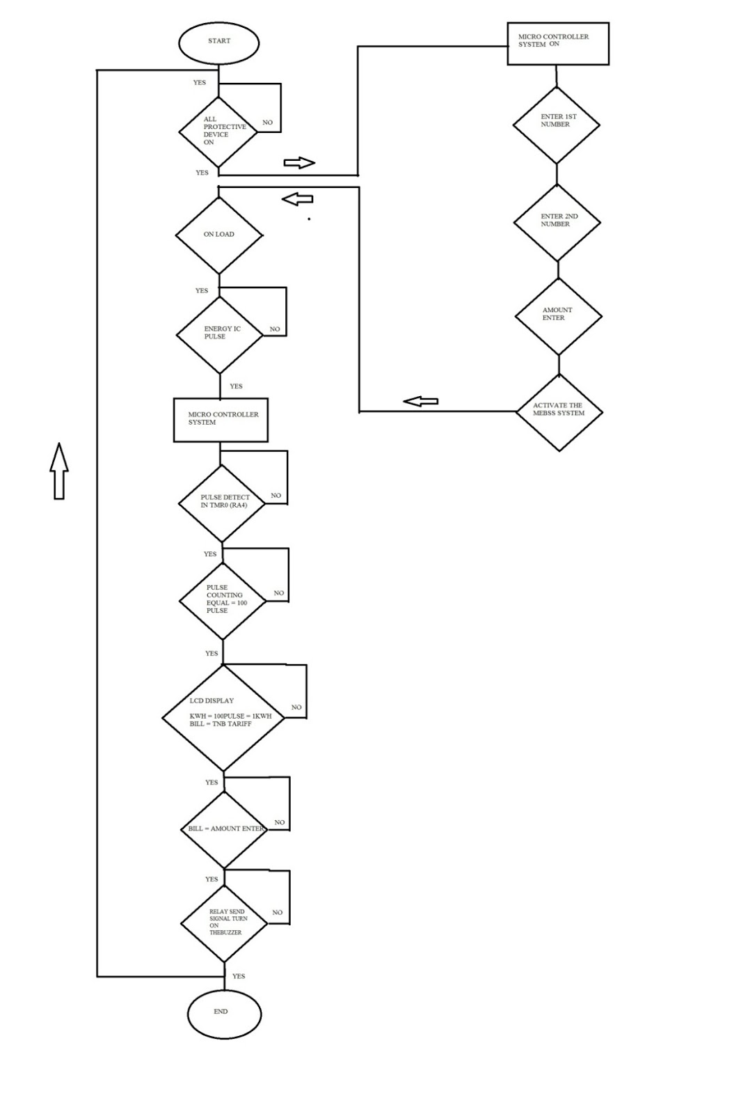
4.2 Flow Chart

4.3 The Body of MEBSS


From the Diagram
above we can see live (red), neutral (black) , and earth (green) connects
the single phase energy meter. The analog energy meter is to show the actual
reading of the energy usage. The output of energy meter will go to the
distribution board were in this distribution board have a protective device
such as Main Switch, Residual Current Circuit Breaker, and Miniature Circuit
Breaker (MCB). The protective device is to protect the circuit from having
short circuit, overload current, earth fault and etc that can damage the
circuit. There have three outputs will go out from distribution board. For the
first output will go to the Step down transformer where in this situation. The
transformers will step down the voltage from 240V AC to 12V AC. The step down
transformer is needed because the circuit cannot handle 240VAC voltage for the
power supply circuit. When a step down voltage is 12V AC it still cannot be a
power supply for the circuit because it is still in AC voltage while the power
supply circuit need is DC voltage. So there has rectifier, to convert AC to DC
voltage. The second output is going to the load where this port is for the load
such as lamp, and other electrical component. And the third output will go to
the circuit where in this circuit it will read and give the reading and display
to the LCD. The LCD will display, energy usage (kWh) and the electric bill
(RM).

4.4 Programming Code of MEBSS
4.4.1 Main Body Program
//--Main
Funtion --
void
main(void)
{
TRISA=0xFF; // Set PORT A as an
INPUT
TRISB=0x0F; // Set PORT B as an
IN/OUTPUT
TRISC=0x0F; // Set PORT C as an IN/OUTPUT
TRISD=0x00; // Set PORT D as Output
T0CS = 1; // Select external Clock source
T0SE = 1; // Increment on falling edge
PSA = 1; // Timer0 without prescaler
TMR0 = -1; // Reset Timer0 Counter
TMR0IE = 1; /* Enable timer0 interrupts
*/
TMR0 = -1; //0x00; /* Timer0 Counter */
GIE=1; // Global interrupt enable
TMR0IF=0; //Clear TMR1 interrupt
flag
PEIE=1; //Peripheral Interrupt
Enable
//--Clear memory of amount set
write_eeprom(50,0);
write_eeprom(51,0);
write_eeprom(52,0);
amountenter();
wait_for_one_press( ); // press RC3
to active the system
lcd_init();
lcd_putc ("Welcome! MEBSS
");
lcd_gotoxy(2,0);
lcd_putc ("is ACTIVATE");
clearmemory();
while (1)
{
currentkwh();
}
}
4.5 Problem
4.5.1
Earth
Fault
When
the running the hardware system with the circuit. I have a problem which is the
earth fault connection. This is an earth fault problem when I turn on the
system only the Residual Current Circuit Breaker (RCCB) is tripped. This RCCB
is functional or operating when only the earth fault is happening. Below
picture shows normal Phase and Neutral wire connections to the meter. Note that
current going through the Phase wire is the same as coming out of the neutral
wire (IP = IN).

An
earth fault means some of the load has been connected to another ground
potential and not the neutral wire. The picture below shows a Partial Earth
Fault Condition where one of the loads is connected to the ground and thus part
of the return current I2 does not go through the meter. Thus the current in the
neutral wire IN, is less than that in the Phase or live wire (IP).

So
to detect this condition, I am using the test pen to check the connection. Then
the problem have encountered, where there have connection from neutral and
earth circuit has been wrong. So the connection change and check with the
circuit diagram. Than no more earth fault happen.
4.5.2 Transformers is Heating
Ihaveg a problem with
the step down transformers where itbecomeseheatedt and haveburnedn smells when
the hardware system isturnedn on. After checking the connection, actually the
connection of transformers is wrong as shown as picture 1. Then I change the
connection as shown picture 2, the transformer heat is normal and do not have
the burn smell.


4.5.3
Neutral
have power ( Line power)
When
the hardware system is turned on, on the neutral connection have power. The
neutral connection it supposes carry no power which is 0V. But when I check the
connection to the hardware system is good, thus on the circuit that having problems.
It's because, the Live (power) connection
is touching with the neutral connection. That's why the neutral
connection is having a power. To eliminate the power of neutral, I must make
sure the live (power) connection not touching the neutral connection. It will
have a big problem when the neutral has a power. The circuit hardware will not stable.
CHAPTER
5
RESULTS
5.1
CIRCUIT DIAGRAM
5.1.1
Power Supply

5.1.2
Energy IC (AD7755)

5.1.3
PIC16f877a ( microcontroller )


5.2
RESULT SIMULATION

From
the result above it show when the amount that consumer want is enter by
pressing the keypad.

After amount is enter the microcontroller will detect and count the pulse at pin RA4. After the count is equal to 100 pulse. The LCD will display the “current kWh” is 1 kWh.
So,
100 pulse = 1kWh
? pulse = 10kWh
? pulse = 10kWh x 100pulse
= 1, 000 pulse.

When
the pulse detect, the system will calculate the kilo-watt hour ( kWh ). After
that, the kWh will convert to electrcic bill. The calculationis refer by tariff
TNB in APPENDIX ( ).

Because
of the amount set is equal to the amount use which is RM2. So, the
microcontroller will send signal to relay to turn on a buzzer.
CHAPTER
6
CONCLUSION
6.1
SUMMARY
Electric
bill is not easy to control or manage because we cannot see how much we use the
energy. With this project Monthly Electric Bill System is useful for all
consumer because this project help consumer to estimate their electrical energy
usage bill at end of the month. It can control or manage by preset the amount
that need by end of the month to the microcontroller. This project will give
advantage knowledge because it combines the in two operations which are
software and hardware. The software are using computer to program into the
microcontroller. This will make we know about the programming instead of
electrical knowledge only. By having the electrical knowledge and combine with
programming knowledge it will make advantage for the future job. This project
can be used in home because all consumers are using electric to operate. They
can save more electric bill instead to waste it.
APPENDIX
i have project just like this. but am not clear about programing. send me yhe whole programe
ReplyDeleteplease i need the full programming code for this project
ReplyDeleteCan I have the code for this project and the proteus simulation?
ReplyDeleteHere is my email Hyper0x00@gmail.com thanks :)
nice project friend. can you send me the codes. i'm designing prepaid energy meter and i'm using ade7755/6
ReplyDelete