Monday 17 September 2012

Heat Sink


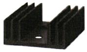
In use, a regulator IC will get quite hot, so a heatsink will need to be attached to it to dissipate the heat.  The type of heatsink you choose depends on the regulator's case style, the amount of heat it must dissipate, and the way in which you wish to mount it.

The examples shown below all suit the 78xx, 78Mxx, and 78Sxx regulator series TO-220 case style. It has a mounting hole for the regulator, and also has a mounting hole for fixing to a board.  

Choosing a heat sink.
Heatsinks are rated by their 'thermal resistance' (Rth) given in °C/W.  For example, a rating of 2°C/W means the heatsink (and therefore the regulator attached to it) will be 2°C hotter than the surrounding air for every 1W of heat it is dissipating.  Note that a lower thermal resistance means a better heatsink.

To determine the heatsink rating required, follow these steps:
  1. Work out the thermal power to be dissipated (P)
    To do this, use the following formula...

    [Equation]

    where P is the power to be dissipated, Vs is the input voltage to the regulator, Vr is the regulated voltage, and I is the current being supplied to the connected circuit.  For example, a 5V regulator supplying 0.5A and powered by 12V supply, would dissipate,

    [Equation]

    Note the use of (12 - 5) = 7V which is the voltage difference across the regulator.  Clearly, lower supply voltages are better so long as they are a few volts above the regulated output.
     
  2. Find out the maximum operating temperature of the regulator (Tmax)
    This can be found from a catalogue or datasheet.  For a typical 78xx series regulator, Tmax = 125°C.
     
  3. Estimate the maximum ambient (surrounding air) temperature (Tair)
    If heatsink is not in a case, Tair = 30°C is reasonable, but inside a case it will be higher (perhaps 40 or 50°C) allowing for everything to warm up in operation.
     
  4. Work out the maximum thermal resistance for heatsink (Rth)
    Use the following formula...

    [Equation]

    where Rth is the thermal resistance, Tmax is the operating temperature from (2) above, Tair is the ambient temperature from (3) above, and P is the power to be dissipated from (1) above.

    So with the example figures given above...

    [Equation]
     
  5. Choose a heatsink with a thermal resistance which is LESS than the value calculated above (remember a lower value means better heatsinking!)  In this case, 10°C/W would be a sensible choice to allow a safety margin.  A 10°C/W heatsink dissipating 3.5W will have a temperature difference of 10 x 3.5 = 35°C so the temperature of the regulator will rise to 30°C + 35°C = 65°C which is safely less than the 125°C maximum.
The heatsink shown on the far right above can dissipate 9.5°C/W and so would be ideal for use in this example.


For Regulation


There are many types of regulator IC and each type will have different pin-outs and will need to be connected up slightly differently.  Therefore, this article will only look at one of the common ranges of regulator, the 78xx series.

There are seven regulators in the 78xx series, and each can pass up to 1A to any connected circuit.  There are also regulators with similar type numbers that can pass a higher or lower current, as shown in the table below.  In addition, variable regulators are available, as are regulators that can provide negative regulation voltages for circuits that require them.

Type Number  Regulation Voltage  Maximum Current  Minimum Input Voltage
78L05+5V0.1A+7V
78L12+12V0.1A+14.5V
78L15+15V0.1A+17.5V

78M05+5V0.5A+7V
78M12+12V0.5A+14.5V
78M15+15V0.5A+17.5V

7805+5V1A+7V
7806+6V1A+8V
7808+8V1A+10.5V
7812+12V1A+14.5V
7815+15V1A+17.5V
7824+24V1A+26V

78S05+5V2A+8V
78S09+9V2A+12V
78S12+12V2A+15V
78S15+15V2A+18V
Ripple voltage.

If using a regulator after the smoothing block of the power supply,then not need to worry about the ripple voltage, since the whole point of using a regulator is to get a stable, accurate, known voltage for your circuits. However, if the ripple voltage is too large and the input voltage to the regulator falls below the regulated voltage of the regulator, then of course the regulator will not be able to produce the correct regulated voltage.  In fact, the input voltage to a regulator should usually be at least 2V above the regulated voltage.  In our power supply circuit, the input to the 7805 regulator is around 12V, and the regulation voltage is 5V, so there is plenty of headroom.  The maximum input voltage to any 78xx regulator is 30V.

Filtering is performed by a large value electrolytic capacitor connected across the DC supply to act as a reservoir, supplying current to the output when the varying DC voltage from the rectifier is falling. The capacitor charges quickly near the peak of the varying DC, and then discharges as it supplies current to the output. Filtering significantly increases the average DC voltage to almost the peak value (1.4 × RMS value).


To calculate the value of capacitor(C),

                                    C = ¼*√3*f*r*Rl
              Where,
                              f = supply frequency,
                              r = ripple factor,
                             Rl = load resistance


78xx pin-out.

The 78xx, 78Mxx, and 78Sxx regulators all have the pin-out shown in the left of figure 1. The 78Lxx series, shown in the right of figure 1. The connection circuit of regulator 78xx, as shown in figure 2. For this project, it use 7805 because give regulated output is 5V and the micro controller only need 5V of source.


IC regulator LM7805


Filtering

This is why the 'smoothing' block is required. Its because the output come from bridge rectifier is not suitable for power supply. So to give the output more smooth we use filtering circuit by using only one capacitor as shown in figure 1 below.


The output waveform in figure 2 shows how smoothing works.  During the first half of the voltage peaks from the rectifier, when the voltage increases, the capacitor charges up.  Then, while the voltage decreases to zero in the second half of the peaks, the capacitor releases its stored energy to keep the output voltage as constant as possible.  Such a capacitor is called a 'smoothing' or 'reservoir' capacitor when it is used in this application.


If the voltage peaks from the rectifier were not continually charging up the capacitor, it would eventually discharge and the output voltage would decrease all the way down to 0V.  The discharging that does occur between peaks gives rise to a small 'ripple' voltage.  The amount of ripple is affected by a combination of three factors:
  • The value of the capacitor.  The larger the capacitor value, the more charge it can store, and the slower it will discharge.  Therefore, smoothing capacitors are normally electrolytic capacitors with values over 470μF.
  • The amount of current used by the circuit.  If the circuit connected to the power supply takes a lot of current, the capacitor will discharge more quickly and there will be a higher ripple voltage.
  • The frequency of the peaks.  The more frequent the voltage peaks from the rectifier, the more often the capacitor will be charged, and the lower the ripple voltage will be.
To calculate the ripple voltage, it will use this formula below.
[Equation]

 Vr = the ripple voltage in Volts
 I = the current taken by the circuit in Amps
 C = the value of the smoothing capacitor in Farads
 F =the frequency of the peaks from the full-wave rectifier, in Hertz.


The ripple voltage should not be more than 10% of Vs - if it is, increase the value of the smoothing capacitor.

So in this project, the value capacitor for filter circuit is 470uF ( as picture below ).


capacitor 470uF


Bridge Rectifier

A Bridge Rectifier ( Full wave Rectifier )

The circuit in figure 3 addresses the second of these problems since at no time is the output voltage 0V.  This time four diodes are arranged so that both the positive and negative parts of the AC waveform are converted to DC.  The resulting waveform is shown in figure 4.


When the AC input is positive, diodes A and B are forward-biased, while diodes C and D are reverse-biased.  When the AC input is negative, the opposite is true - diodes C and D are forward-biased, while diodes A and B are reverse-biased.

One disadvantage of the full-wave rectifier is that there is a voltage loss of 1.4V across the diodes.  Why not 2.8V as there are four diodes, that is because there is only two of the diodes are passing current at any one time.

While the full-wave rectifier is an improvement on the half-wave rectifier, its output still is not suitable as a power supply for most circuits since the output voltage still varies between 0V and Vs-1.4V.  So, if you put 12V AC in, you will 10.6V DC out.


The formula Bridge full wave Rectifier is,


 Full wave   Bridge
Number of   diodes


4

PIV of diodes


Vm


D.C output voltage

2Vm/phi


Vdc,at
no-load                 

0.636Vm


Ripple factor

0.482

    Ripple     
   frequency

2f

  Rectification
   efficiency

0.812

  Transformer
   Utilization
   Factor(TUF)  

0.812

RMS voltage Vrms
Vm/√2


A bridge rectifier makes use of four diodes in a bridge arrangement to achieve full-wave rectification. This is a widely used configuration, both with individual diodes wired as shown and with single component bridges where the diode bridge is wired internally. So, in this project it will use 4 x 1N4001 diode (as picture below).


Diode type 1N4001


Step down transformers


A transformer consists of two coils (often called 'windings') linked by an iron core, as shown in figure below. There is no electrical connection between the coils, instead they are linked by a magnetic field created in the core.
Step-down transformers


Step down transformers is to reduce a voltage. Most power supplies use a step-down transformer to reduce the dangerously high mains voltage to a safer low voltage.   The input coil is called the primary and the output coil is called the secondary. 

For this project, it will use a step down transformers that give output 9V or 12V as picture below.


The ratio of the number of turns on each coil, called the turn’s ratio, determines the ratio of the voltages. A step-down transformer has a large number of turns on its primary (input) coil which is connected to the high voltage mains supply, and a small number of turns on its secondary (output) coil to give a low output voltage.

Below are transformers formula,

Turns ratio = Vp/ VS = Np/NS

Power Out= Power In

VS X IS=VP X IP

Vp = primary (input) voltage
Np = number of turns on primary coil
Ip  = primary (input) current     


Transformers have two great advantages over other methods of changing voltage:
  1. They provide total electrical isolation between the input and output, so they can be safely used to reduce the high voltage of the mains supply.
  1. Almost no power is wasted in a transformer. They have a high efficiency (power out / power in) of 95% or more.

For Regulated Power Supply


Regulated Power Supply:


1)       Step Down Transformer
2)      Bridge Rectifier
3)      Filter Circuit (Smoothing )
4)      Regulator  section


Sunday 16 September 2012

Methodology


a)      Power Supply
-          Transformer to step down voltage from 240V to 9V.
-          Bridge rectifier to convert from AC to DC voltage.
-          IC Regulated (LM7805) to regulate the voltage 5V to supply to Microcontroller.

b)      Microcontroller PIC16f877a
-          Using MPLAB program to write a C language to program to microcontroller.
-          Using a Proteus program to design a circuit.

c)      EEPROM
-          To store the data

d)     Buzzer
-          To produce a sound on the certain operation.

e)      LCD
-          To display a digital energy meter and the electric bill (RM) in digital.

f)       Voltage and Current sensor
-          To sense the energy usage.

g)      Miniature Circuit Breaker

-          To trip the connection

Literature Review


After doing a research, there have many information and project that have connected to the purposed project. In a present day there already change from the analog energy meter to a digital energy meter in a certain place and the other places still have using the analog energy meter. Now, according to Md. Mejbaul Haque project that I have research. He creates a single phase digital prepaid energy meter based on two microcontrollers and a single phase energy meter IC. This digital prepaid energy meter does not have any rotating parts. The energy consumption is calculated using the output pulses of the energy meter chip and the internal counter of microcontroller (ATmega32). A microcontroller (ATtiny13) is used as a smart card and the numbers of units recharged by the consumers are written in it. A relay system has been used which either isolates or establishes the connection between the electrical load and energy meter through the supply mains depending upon the units present in the smart card. Energy consumption (kWh), maximum demand (kW), total unit recharged (kWh) and rest of the units (kWh) are stored in the ATmega32 to ensure the accurate measurement even in the event of an electrical power outage that can be easily read from a 20×4 LCD. As soon as the supply is restored, energy meter restarts with the stored values. A single phase prepaid energy meter prototype has been implemented to provide measurement up to 40A load current and 230V line to neutral voltage.Necessary program for microcontrollers are written in c-language and compiled by Win-AVR libc compiler.

            For my opinion, using a card reader is hard for us to reload the prepaid card if the card is empty. Need to make sure the card has credit, if we want use an electrical. For my project, the most important contributions of other related projects/findings for my project is to make sure the consumer know how much they use the energy, besides this project is already convert from energy usage (kWh) to Ringgit Malaysia (RM),so the consumer will know how much for electric bill in a month that need to pay. Other than that, this project have saving system, so they set the amount if they want to budget in an electric bill by set how much they want to pay into the system.

Problem Statement


In every house the energy meter only show the watt usage per hour. That why the consumer always did not know how much electrical energy use in a month because there is no system to alert them. Beside that the consumer did not know how to read the energy meter. So, the consumer did not know how much they need to pay for the electrical bill by the end of the month. Other than that, because of the consumer did not how to read the energy meter, it is so hard for them to budget their electrical bill.

 So, with this Monthly Electric Bill Saving System (MEBSS) project, it will help people to know how much they use and also they can set the amount (RM) they want in electrical bill at the end of month. It has LCD that display everything such as energy usage in kWh unit and the bill need to pay in RM unit.  This system is already convert from energy usage kWh to a billing in ringgit Malaysia (RM) by refer a tariff domestic from TNB. They also can set the amount (RM) in this MEBS system. It will trip the current at main distribution board (MSB) in that house if the amount is reached. If it trip early of the month they can add another amount (RM) in MEBS System. With this system they can budget for electrical bill and save money.

The Introduction


Now days, people do not know how much electrical energy use in a month because there is no system to alert them. So, with this Monthly Electric Bill Saving System (MEBSS) project, it will help people to know how much they use and also they can set the amount (RM) they want in electrical bill at the end of month. It has LCD that display everything such as energy usage in kWh unit and the bill need to pay in RM unit.  This system is already convert from energy usage kWh to a billing in ringgit Malaysia (RM) by refer a tariff domestic from TNB. They also can set the amount (RM) in this MEBS system. It will trip the current at main distribution board (MSB) in that house if the amount is reached. If it trip early of the month they can add another amount (RM) in MEBS System. With this system they can budget for electrical bill and save money.

For example:
 If Mr. A wants to pay only RM20 at the end of month, so Mr. A need to set RM20 in MEBSS. But if the MEBSS trip before end of the month, then Mr A need to add the amount at the MEBSS. Let say, Mr. A add another RM10, so, the calculation for that month is RM20 (early setting) + RM10 (after setting) = RM30. So Mr. A will know that he needs to pay RM30 for electrical bill.

This project is fully control by embedded system a program that program in microcontroller PIC16f877a. An embedded system is a special-purpose system in which the computer is completely program by or dedicated to the device or system it controls. Unlike a general-purpose computer, such as a personal computer, an embedded system performs one or a few predefined tasks, usually with very specific requirements. Since the system is dedicated to specific tasks, design engineers can optimize it, reducing the size and cost of the product. Embedded systems are often mass-produced, benefiting from economies of scale.